Comintel Biogen Advance Biomass Gasification System
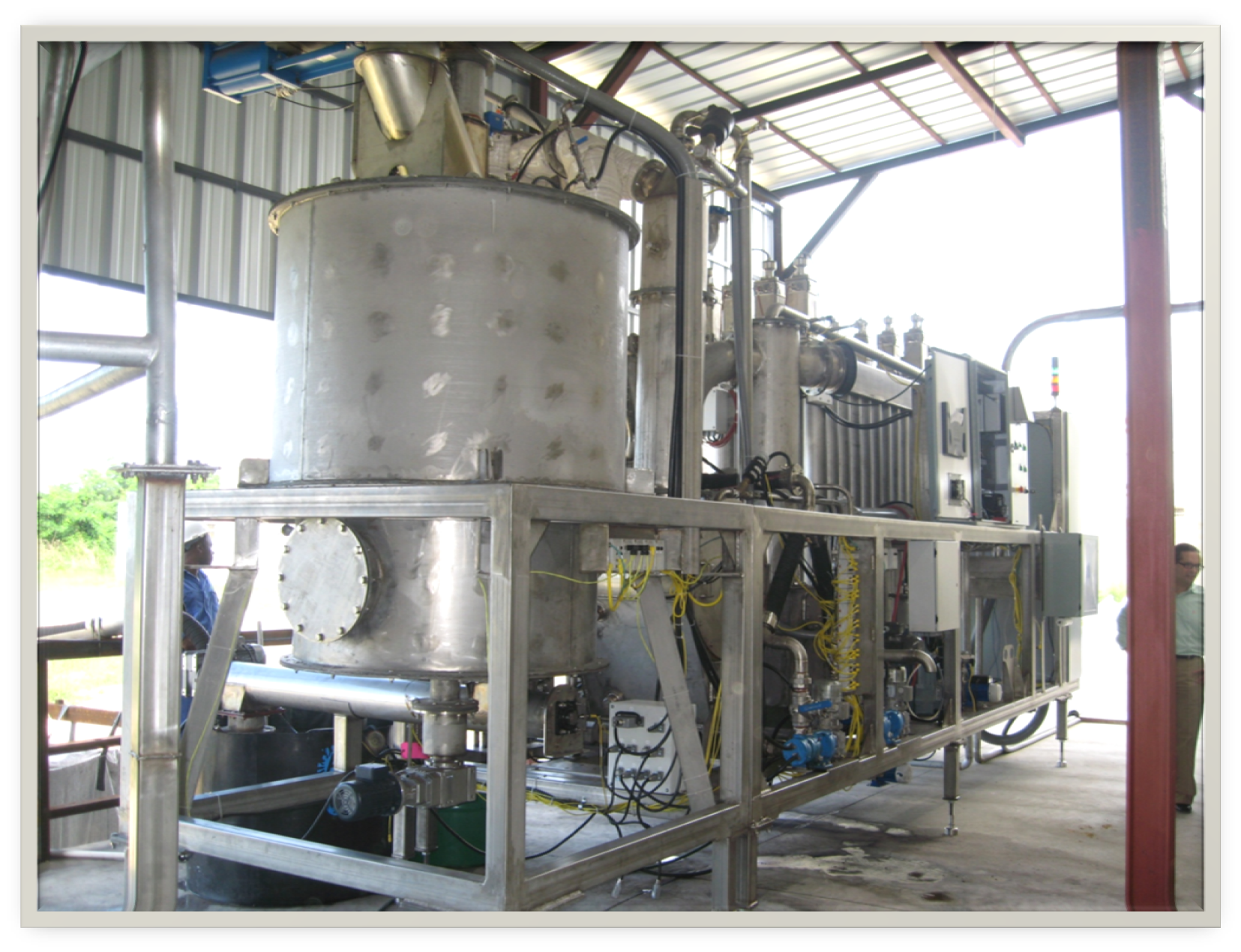
System Specification
| MODEL G1300E GASIFIER UNIT | |
|---|---|
| Maximum Biomass Consumption | 750 kg per hour |
| Synthesis Gas production | 1400 M3/hr, (45ºC) |
| Typical Synthesis Gas Caloric Value (LHV) | 4.75 MJ/ M3 |
| Typical Efficiency, Biomass to Synthesis Gas | >75% (Not including CHP applications) |
| Maximum Electrical Output | 750 kW |
| Overall end-to-end Electrical Efficiency dependent upon generator solution chosen | Ranges 24% - 28%. Efficiency will increase when CHP is applied. |
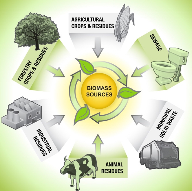
What’s Gassification?
|
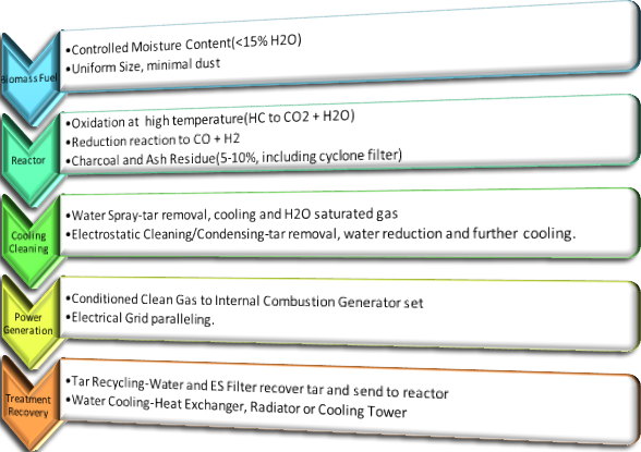
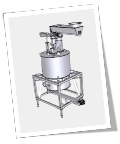
The gasification process starts with a high temperature reactor, where dried biomass (<15% moisture content) is converted into synthesis gas. Gasification reactors resemble tube furnaces, with a fuel inlet at the top and a grating at the bottom. A primary difference between a furnace and a gasifier is the stratification of different layers, or zones inside the reactor. With a furnace, the combustion is at the bottom; near the grating; fuel is added to the top, with gases and smoke exhausting out the top. With a gasifier, there is also a combustion, or oxidation zone, however it is positioned higher up in the tube, and there is another zone below, called the reduction zone, where the synthesis gas is produced. Basically, in the oxidation zone the fuel is initially burned same as in a furnace, with the hydrocarbons in the fuel converting to carbon dioxide (CO2) and water vapor (H2O). This reaction is exothermic and produces a large amount of energy as heat; but in the reduction zone below, the CO2 and H2O convert to carbon monoxide gas (CO) and hydrogen gas (H2) These reactions are endothermic and need a lot of energy to take place; the oxidation zone directly above supplies the necessary energy to form these gases. These two gases are the main combustible ingredients of the synthesis gas. Other combustible hydrocarbon gases like methane (CH4) and others are also present from incomplete combustion. These are called pyrolysis gases, and they increase the caloric value of the synthesis gas. There are typically small amounts of other more complex hydrocarbons (tars) also present in the gas due to incomplete combustion, along with the incombustible components; Nitrogen gas (N2), and typically some unreacted CO2 and H2O. So in a nutshell, a gasifier is a type of furnace arranged so that there is a reduction zone underneath the traditional oxidation zone. Another major difference between a furnace and a gasifier is that there is no exhaust of gases and smoke; all the volatiles emitted become synthesis gas, with no other exhaust emitted. Source : Biogendr Website |